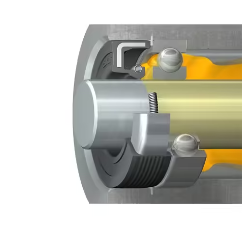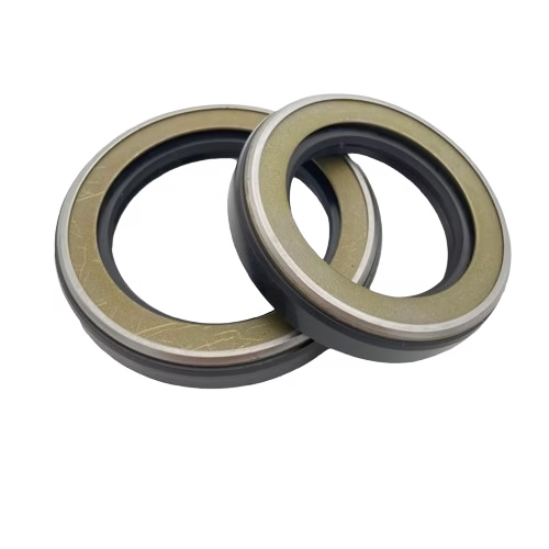
A rotary tiller oil seal replacement is not simply a matter of removing a leaking seal and installing another one with the same dimensions. In agricultural machinery, oil seal performance depends on the complete sealing system: the shaft surface, bearing condition, housing bore, gearbox pressure, lubricant, seal structure, installation method, and external contamination.
This distinction is important for agricultural machinery repair companies, rotary tiller manufacturers, gearbox rebuilders, parts distributors, and aftermarket buyers. When leakage returns shortly after replacement, repeatedly ordering the same oil seal may increase repair costs without correcting the real problem.
This guide explains how to diagnose rotary tiller gearbox oil leaks, identify the correct replacement oil seal, inspect related components, select a suitable material and structure, and determine whether a standard seal or customized sealing solution is required.
Quick Answer
A rotary tiller oil seal should be replaced when lubricant appears around the tine shaft, rotor shaft, gearbox input shaft, output shaft, side-drive shaft, or PTO connection.
Before installing a new seal:
- Confirm the exact leakage source.
- Verify the seal size, structure, material, and lip direction.
- Inspect the shaft for grooves, rust, pitting, and burrs.
- Check the bearing for excessive radial or axial movement.
- Measure and clean the housing bore.
- Check whether the gearbox breather is blocked.
- Confirm that the lubricant and operating temperature are compatible with the seal compound.
The spring-loaded primary lip normally faces the lubricant being retained. An auxiliary dust lip normally faces the external contamination side.
The basic replacement process is:
- Identify the leaking shaft and confirm the oil source.
- Drain and inspect the gearbox lubricant.
- Remove the necessary guards, hubs, covers, or shaft components.
- Extract the old oil seal without damaging the housing.
- Inspect the shaft, bearing, housing bore, and breather.
- Confirm the replacement seal dimensions, structure, and material.
- Lubricate and install the new seal in the correct direction.
- Reassemble the rotary tiller and refill it with the specified oil.
- Test under light load and recheck for leakage.
Replacing only the seal will not provide a durable repair if the shaft is grooved, the bearing is loose, the housing bore is damaged, the breather is blocked, or the replacement seal does not match the operating conditions.
Where Rotary Tiller Oil Seals Are Used
A rotary tiller may contain several radial shaft seals. Each location has different speed, contamination, alignment, pressure, and mechanical loading conditions.
Tine Shaft or Rotor Shaft Seals
Tine shaft seals retain gearbox or side-drive lubricant while preventing soil, dust, water, mud, sand, and crop fibers from entering around the rotating shaft.
This is often the most demanding seal location on a rotary tiller because it operates close to the ground and is directly exposed to:
- Abrasive soil
- Wet mud
- Stones
- Wrapped grass
- Roots and crop residue
- Wire
- Fertilizer residue
- Wash water
- Seasonal corrosion
Contamination can wear through the external dust lip and eventually reach the primary oil-retaining lip. Wrapped fibers may also generate heat, deform the lip, or pull the sealing edge away from the shaft.
For this location, buyers should evaluate not only the seal dimensions but also the dust-exclusion structure. A conventional single-lip seal may be adequate in a protected housing, while a double-lip, reinforced, cassette, or guarded design may be more suitable in severe field conditions.
Gearbox Input Shaft and PTO Shaft Seals
The input shaft transfers power from the tractor PTO driveline into the rotary tiller gearbox.
The seal must retain lubricant while operating under:
- Shaft rotation
- Driveline vibration
- Coupling movement
- Temperature changes
- Misalignment
- Variable torque
- Possible axial loading
Incorrect driveline angles, worn universal joints, bent input shafts, damaged couplings, or loose gearbox mounting points can create shaft movement that the oil seal cannot follow consistently.
A leaking input shaft seal may therefore indicate a driveline or bearing problem rather than an unsuitable seal material.
Intermediate and Side-Drive Shaft Seals
Oil seals may also be installed in:
- Chain-drive housings
- Side gearboxes
- Intermediate shafts
- Bearing carriers
- Auxiliary transmission sections
- Output shaft supports
These positions may be less exposed than the tine shaft, but they can still fail because of bearing wear, housing distortion, lubricant contamination, chain loading, or incorrect assembly.
Rotary Tiller Seal Location and Operating Risk
| Seal location | Main function | Typical contaminants | Common failure risk |
|---|---|---|---|
| Tine or rotor shaft | Retains lubricant and blocks soil | Mud, sand, fibers, water | Shaft wear and lip abrasion |
| Gearbox input shaft | Seals the rotating drive input | Dust, oil mist, heat | Misalignment and vibration |
| Side-drive shaft | Retains chain or gearbox lubricant | Soil and debris | Bearing play or housing damage |
| PTO connection | Prevents lubricant leakage | Dust and moisture | Coupling movement and shaft wear |
Signs That the Oil Seal Needs Replacement
Visible Oil Leakage
Visible oil around a rotating shaft is the most common indication of a failed or overloaded seal.
Typical signs include:
- Oil collecting around the shaft or bearing carrier
- Wet soil adhering to the seal area
- Oil streaks on the gearbox casing
- Oil being thrown outward by shaft rotation
- Leakage appearing after field operation
- Leakage increasing as the gearbox becomes warm
The leakage pattern can help with diagnosis.
Leakage that appears mainly after operation may be related to:
- Reduced lubricant viscosity at operating temperature
- Increased gearbox pressure
- Bearing movement under load
- Shaft runout
- Overfilling
Before ordering a replacement, clean the gearbox and verify that the oil is actually passing through the shaft seal. A leaking gasket, drain plug, inspection cover, breather, or cracked casting can produce a similar oil pattern.
Falling Gearbox Oil Level
Repeated lubricant loss can damage:
- Gears
- Chains
- Bearings
- Bushings
- Shaft surfaces
A low lubricant level may lead to noise, overheating, accelerated wear, and eventual gearbox failure.
However, buyers and repair companies should confirm whether the oil loss comes from:
- A shaft seal
- A drain or level plug
- A cover gasket
- A damaged housing joint
- A cracked casting
- Breather overflow
- Incorrect oil filling
An overfilled gearbox may also force oil through otherwise serviceable seals.
Dirt or Water Entering the Gearbox
An oil seal must prevent both lubricant loss and contaminant entry.
Possible warning signs include:
- Milky or cloudy gearbox oil
- Water droplets in drained oil
- Abrasive particles
- Rust on internal components
- Sludge
- Bearing noise
- Increased operating temperature
When contamination has entered the gearbox, replacing the seal alone may not be sufficient. The lubricant should be replaced, and the internal condition of the gearbox should be assessed before the machine returns to service.
Physical Seal Damage
After removal, inspect the old seal for:
- A hardened or cracked sealing lip
- A torn dust lip
- Lip deformation
- An exposed or displaced garter spring
- Uneven contact marks
- Corrosion on the metal case
- A polished outside diameter
- Evidence that the seal rotated in the housing
The condition of the failed seal can help identify the cause.
For example:
- A cut lip suggests installation damage.
- A hardened lip may indicate heat aging.
- A polished outside diameter may indicate movement in the housing bore.
- Heavy external wear may indicate inadequate contamination exclusion.
- A displaced spring may indicate installation damage or severe shaft movement.
Why Rotary Tiller Oil Seals Fail
Shaft Grooves, Rust, and Surface Damage
A radial oil seal runs continuously on a narrow shaft contact track. Over time, this track may develop a groove.
If the replacement seal is installed at the same depth, the new lip may run directly in the worn groove. The groove then acts as a leakage path, even when the new seal is dimensionally correct.
Shaft damage may be caused by:
- Soil abrasion
- Corrosion during seasonal storage
- Wrapped wire, roots, or crop fibers
- Incorrect seal removal tools
- Burrs on shaft shoulders
- Previous seals running on the same track
- Poor machining or repair work
- Impact damage
The sealing surface should be smooth, round, and free from pitting, burrs, corrosion, and directional machining marks.
A visible contact track does not always mean the shaft must be replaced. Buyers should determine whether the area is only polished or whether measurable material has been removed.
Bearing Wear and Excessive Shaft Movement
A rotary shaft seal can accommodate only limited shaft runout, eccentricity, and misalignment.
A worn or incorrectly fitted bearing may allow:
- Radial shaft movement
- Axial movement
- Shaft wobble
- Misalignment between the shaft and housing
- Increased vibration under tine load
The shaft may feel acceptable when the machine is stationary but move excessively during field operation.
This is why a leaking seal may be a symptom of bearing failure rather than the primary problem. Repeatedly replacing the seal without correcting the bearing normally leads to another leak.
Blocked Gearbox Breather or Excessive Internal Pressure
As the gearbox heats during operation, the oil and trapped air expand. A functioning breather allows the internal pressure to equalize.
When the breather is blocked by mud, paint, rust, or debris, pressure can push lubricant past the sealing lip. In more severe cases, the seal may move outward from the housing.
Before replacing the oil seal, check:
- Whether the breather passage is open
- Whether the cap or filter is blocked
- Whether the breather is correctly installed
- Whether the gearbox has been overfilled
- Whether oil foaming is occurring
A higher-cost seal material will not solve leakage caused by excessive internal pressure.
Incorrect Seal Material
Seal material selection should be based on the actual operating environment, not only on a generic temperature chart.
Material-related failure may include:
- Hardening from heat aging
- Swelling in an incompatible lubricant
- Softening caused by fluid additives
- Cracking after extended exposure
- Excessive wear
- Loss of flexibility during cold startup
The temperature at the sealing lip may be higher than the measured bulk oil temperature because friction generates heat at the shaft contact.
Material selection should consider:
- Lubricant type
- Lubricant additive package
- Continuous temperature
- Peak temperature
- Shaft speed
- Operating duration
- External contamination
- Storage conditions
- Required service interval
Incorrect Installation
Installation damage can cause immediate or early leakage.
Common errors include:
- Installing the seal backward
- Starting the seal at an angle
- Hammering directly on the seal
- Driving through the flexible lip
- Installing the lip dry
- Cutting the lip on a keyway or spline
- Distorting the metal case
- Installing the seal too deeply
- Using the wrong outside diameter
- Dislodging the garter spring
- Reusing a removed seal
Installation force should be applied evenly to the rigid outside section of the seal. Sharp shaft features should be covered with a smooth protective sleeve before the lip passes over them.
Contamination Around the Tine Shaft
Mud, sand, grass, wire, roots, and crop fibers can damage the oil seal from the outside.
External contamination may:
- Abrade the dust lip
- Lift the auxiliary lip
- Trap moisture against the shaft
- Cause corrosion
- Generate frictional heat
- Push debris toward the primary lip
Where contamination exceeds the capability of a standard dust lip, the sealing system may require:
- An external guard
- A stronger exclusion lip
- A labyrinth feature
- A cassette or unitized seal
- More frequent debris removal
- A revised housing design
Rotary Tiller Oil Seal Failure Analysis
| Symptom | Possible cause | Recommended check | Corrective action |
|---|---|---|---|
| New seal leaks immediately | Reversed seal or damaged lip | Inspect orientation and shaft entry path | Replace and reinstall correctly |
| Leakage returns after several hours | Shaft groove or bearing movement | Measure the shaft and check bearing play | Repair the shaft or replace the bearing |
| Seal moves outward | Blocked breather or excessive pressure | Inspect ventilation and oil level | Clean the breather and correct the fill level |
| Mud enters the gearbox | Damaged dust lip or inadequate structure | Inspect the external contamination barrier | Use a protected or double-lip design |
| Seal rotates in the housing | Loose or damaged housing bore | Measure bore size and condition | Repair the housing or develop another fit |
Tools and Parts Required for Replacement
The exact equipment depends on the tiller model and gearbox design.
Essential Tools
Typical tools include:
- Manufacturer service manual
- Socket and wrench set
- Puller for hubs or bearing carriers
- Seal removal tool
- Seal driver or flat mandrel
- Torque wrench
- Caliper or micrometer
- Bore measuring tools
- Cleaning materials
- Drain pan
- Compatible assembly lubricant
- Protective sleeve for splines, threads, or keyways
Replacement Parts and Consumables
Prepare the parts that may be disturbed during disassembly:
- Correct rotary shaft oil seal
- Specified gearbox oil
- Replacement gaskets and O-rings
- Bearings where required
- Retaining rings and spacers
- Shaft repair sleeve where appropriate
- Manufacturer-approved thread-locking compound
- Outside-diameter retaining compound only when specified
Adhesive should not be used as a substitute for repairing a severely worn or oversized housing bore.
Safety Preparation
Disconnect the tractor or power source, support the rotary tiller securely, prevent tine movement, allow the gearbox to cool, and remove loose soil before opening the assembly.
Heavy hubs, tine shafts, and bearing carriers should be supported with suitable lifting equipment.
How to Identify the Correct Replacement Oil Seal
Read the Existing Seal Markings
An oil seal may be marked with:
- Inside diameter
- Outside diameter
- Width
- Material code
- Manufacturer code
- Seal profile
- Dust-lip designation
For example:
35 × 52 × 8 mm
This normally indicates:
- 35 mm shaft diameter
- 52 mm housing bore diameter
- 8 mm seal width
Do not use a distorted or damaged old seal as the only dimensional reference. The outside diameter may change during removal, and the lip opening cannot be used to determine the original shaft size accurately.
Measure the Shaft and Housing Bore
Measure:
- Shaft diameter at an unworn section
- Shaft diameter at the lip contact track
- Housing bore diameter
- Available seal width
- Installation depth
- Distance to shoulders or bearings
- Shaft chamfer
- Housing lead-in condition
Compare the measurements with:
- The machine service manual
- The OEM part number
- The original engineering drawing
- A known undamaged component
- The gearbox manufacturer’s specification
Confirm the Seal Structure
Common options include:
Single-lip oil seal
Used mainly for lubricant retention where external contamination is limited.
Double-lip oil seal
Includes an auxiliary lip to reduce dust, mud, and dirt entry.
Rubber-covered outside diameter
Provides static sealing against the housing and can accommodate minor surface imperfections.
Metal-cased outside diameter
Provides a rigid press fit but normally requires a controlled housing bore.
Reinforced agricultural seal
May use a stronger case, lip structure, or contamination barrier.
Cassette or unitized seal
Combines sealing and running surfaces in a protected assembly for severe contamination, shaft movement, or long-life OEM applications.
Many tine shaft positions benefit from an auxiliary dust lip. However, the original housing design, available width, shaft surface, and friction level must be checked before changing the seal structure.
Confirm Lip Direction
The spring-loaded primary sealing lip normally faces the oil or grease being retained.
The auxiliary dust lip normally faces outward toward soil, mud, and debris.
Reverse installation can cause immediate leakage because the main lip geometry is facing away from the lubricant.
Match the OEM Part Number Carefully
Two seals with identical dimensions may still differ in:
- Lip geometry
- Spring design
- Rubber compound
- Pressure capability
- Rotation-sensitive features
- Outside-diameter construction
- Dust-exclusion structure
- Installation depth
A replacement should not be approved only because the shaft diameter, housing diameter, and width are the same.
Information Needed to Select a Replacement Seal
| Required information | Why it matters |
|---|---|
| Shaft diameter | Determines the seal inside diameter and lip interference |
| Housing bore diameter | Determines the required outside-diameter fit |
| Seal width | Confirms the available axial space |
| Shaft speed | Influences friction, temperature, and wear |
| Lubricant type | Determines rubber compatibility |
| Operating temperature | Guides compound selection |
| Mud and dust exposure | Determines exclusion-lip requirements |
| Shaft condition | Shows whether repair is required |
| OEM part number | Helps verify the original specification |
| Failure pattern | Helps determine whether the original structure is suitable |
For distributors and repair companies, recording the seal size, structure, material, installation position, and failure reason helps reduce repeated wrong orders and improves repeat supply reliability.
This information is especially valuable when the same rotary tiller model uses different seals in the input shaft, side-drive housing, and tine shaft positions.
Selecting the Right Seal Material
NBR for Standard Agricultural Gearbox Service
Nitrile rubber, commonly identified as NBR, is widely used in mineral-oil-lubricated agricultural gearboxes.
Its practical advantages include:
- Good compatibility with many mineral oils
- Useful wear resistance
- Wide availability
- Economical replacement cost
- Established use in rotary shaft seals
NBR is often suitable when:
- The lubricant is conventional
- The gearbox temperature is moderate
- The original seal provided acceptable life
- Shaft speed is within the intended range
- External contamination is controlled by the seal structure
NBR compounds are not all identical. Formulation, hardness, lubricant additives, speed, and exposure time influence actual performance.
FKM for Higher Temperatures or Demanding Fluids
FKM may be considered when the application involves:
- Higher continuous gearbox temperatures
- Greater shaft speed
- Demanding lubricant additives
- Extended service intervals
- Recurring heat-aging failures
- Chemical exposure unsuitable for standard NBR
FKM is not automatically the best choice for every rotary tiller.
A more expensive compound will not correct:
- Shaft grooves
- Bearing movement
- Incorrect lip direction
- Mud packed around the shaft
- A damaged housing bore
- A blocked breather
In a slow tine shaft exposed to abrasive mud, the exclusion structure may have a greater effect on service life than upgrading from NBR to FKM.
HNBR and Specialized Compounds
HNBR may be evaluated where improved heat aging, wear resistance, and mechanical strength are required.
Specialized compounds may also be appropriate for:
- Unusual lubricants
- Wide temperature cycles
- High mechanical loading
- Mixed oil and chemical exposure
- Extended-life OEM programs
- Recurring field failures
For OEM projects, the final compound should be selected using complete application data and validated under representative operating conditions.
Oil Seal Material Comparison for Rotary Tillers
| Material | Typical strengths | Main limitations | Suitable use |
|---|---|---|---|
| NBR | Economical and compatible with many mineral oils | Lower heat-aging capability than premium compounds | Standard gearbox and shaft sealing |
| FKM | Strong heat and chemical resistance | Higher cost and not always necessary | High-temperature or demanding lubricant service |
| HNBR | Improved heat, strength, and wear properties | Higher cost and lower general availability | Heavy-duty OEM or extended-life applications |
| Custom compound | Optimized for specific fluids and operating conditions | Requires application data and validation | Specialized machinery or recurring failures |
Material note: Exact operating temperature limits should come from the specification for the selected rubber compound rather than a generic rating for the complete material family.
Step-by-Step Rotary Tiller Oil Seal Replacement
The exact replacement procedure varies by rotary tiller model, gearbox design, and manufacturer service instructions.
For repair companies, distributors, and aftermarket suppliers, the key requirement is to record the original seal structure, failure cause, dimensions, and installation position before the assembly is rebuilt. This prevents the repair information from being lost and helps establish a reliable replacement specification for future orders.
Step 1 — Confirm the Actual Leakage Source
Clean the gearbox and shaft area.
Where safe, rotate or operate the machine briefly and determine whether the oil comes from:
- The shaft seal
- A housing gasket
- The drain plug
- The level plug
- An inspection cover
- A gearbox joint
- A cracked casting
- Breather overflow
Do not begin major disassembly until the leakage source has been reasonably confirmed.
Step 2 — Record the Existing Assembly
Before removing components, take photographs and record:
- Seal direction
- Installation depth
- Spacer positions
- Washer positions
- Bearing-carrier orientation
- Retaining-ring locations
- Shaft hardware sequence
- Guard and shield arrangement
For repair companies handling multiple machines, this information can become part of a repeatable service record.
Step 3 — Drain and Inspect the Gearbox Lubricant
Drain the oil into a clean container.
Inspect it for:
- Metal particles
- Water contamination
- Milky appearance
- Burnt odor
- Excessive sludge
- Soil contamination
- Incorrect quantity
Metal debris may indicate gear, bearing, or chain damage. Water-contaminated oil may require internal cleaning rather than only a seal replacement.
Step 4 — Remove the Required Shaft Components
Depending on the machine design, it may be necessary to remove:
- Tines
- Hubs
- Covers
- Pulleys
- Bearing carriers
- Spacers
- Retaining rings
- Shaft sections
Avoid:
- Striking the sealing surface
- Pulling against unsupported castings
- Scratching the shaft with gripping tools
- Damaging splines or threads
- Mixing matched spacers
- Losing shim positions
Step 5 — Remove the Old Oil Seal
Use a proper seal puller where possible.
Extraction screws may be used in some assemblies, provided they cannot contact the bearing, shaft, or internal components.
Protect:
- The housing bore
- Shaft surface
- Bearing
- Seal shoulder
- Adjacent gasket surfaces
Do not pry directly against a soft aluminum housing without suitable protection.
A removed seal should normally not be reused. Extraction may deform the case, sealing lip, or garter spring even when the damage is not obvious.
Step 6 — Inspect the Shaft, Bearing, Housing, and Breather
Shaft Inspection
Check for:
- Wear grooves
- Rust
- Burrs
- Pitting
- Diameter loss
- Spiral machining marks
- Scratches
- Wrapped debris
Measure the shaft at both an unworn section and the sealing track.
Bearing Inspection
Check for:
- Rough rotation
- Noise
- Excessive radial movement
- Axial movement
- Heat discoloration
- Contaminated lubricant
- Loose inner or outer fit
A bearing that feels acceptable without load may move excessively when controlled force is applied to the shaft.
Housing Bore Inspection
Check for:
- Scratches
- Corrosion
- Ovality
- Cracks
- Burrs
- Loose seal fit
- Residual adhesive
- Previous removal damage
A seal that rotates in the housing cannot maintain a reliable static seal.
Breather Inspection
Confirm that the breather is open, clean, correctly installed, and not blocked by mud or paint.
Step 7 — Prepare the New Seal and Installation Surfaces
Before installation:
- Confirm the part number and dimensions again.
- Clean the shaft and housing.
- Lightly lubricate the primary lip with compatible oil.
- Protect the lip from splines, threads, keyways, and sharp shoulders.
- Keep dirt away from the sealing edge and spring.
- Apply outside-diameter sealant only when specified.
Do not use excessive grease between dual lips unless the seal or equipment specification requires it.
Step 8 — Install the New Oil Seal
Install the spring-loaded primary lip toward the lubricant.
Then:
- Align the seal squarely with the housing.
- Use a driver that contacts the rigid outside section.
- Apply even pressure.
- Install to the specified or recorded depth.
- Do not press through the flexible lip.
- Confirm that the seal is not tilted.
- Verify that the garter spring remains in place.
Do not hammer one side of the seal and then the other. Uneven driving can distort the case and damage the housing fit.
Step 9 — Reassemble the Rotary Tiller
During reassembly:
- Replace damaged gaskets and O-rings.
- Reinstall spacers in the recorded sequence.
- Replace damaged retaining hardware.
- Follow the manufacturer’s torque requirements.
- Confirm that the shaft rotates correctly.
- Reinstall all guards and shields.
Step 10 — Refill and Test
Use the gearbox oil grade specified by the machine manufacturer.
Then:
- Fill to the correct level.
- Avoid overfilling.
- Rotate the shaft slowly where possible.
- Check for binding.
- Inspect for immediate leakage.
- Operate the machine under light load.
- Stop and inspect the seal area.
- Recheck the oil level after the first operating period.
Clean any assembly oil from the external area before final testing so that fresh leakage can be identified correctly.
When Repeated Leakage Is Not a Seal Quality Problem
Repeated leakage does not automatically mean that the replacement oil seal is poor quality.
In rotary tillers, repeated leakage may result from:
- Shaft grooves
- Bearing movement
- A blocked breather
- Housing bore damage
- Overfilling
- Incorrect lip direction
- Installation damage
- Shaft misalignment
- Mud packed around the shaft
- An unsuitable seal structure
Before changing suppliers or selecting a more expensive rubber material, buyers should inspect the complete sealing system.
This is particularly important for distributors and repair companies. When the same replacement seal repeatedly fails across several machines, the correct response is not always to reorder a harder or more expensive seal. The supplier may need application photographs, failed-seal samples, shaft measurements, lubricant information, and details of the operating environment.
A structured failure review helps separate three different issues:
- A defective or incorrect seal
- A damaged surrounding component
- A seal design that is unsuitable for the application
This distinction reduces unnecessary supplier changes, repeated warranty claims, and ineffective repairs.
What to Do When a New Oil Seal Still Leaks
Check for Installation Damage
If leakage begins immediately, inspect for:
- A folded lip
- A cut sealing edge
- A displaced spring
- Reverse installation
- Uneven seating
- Incorrect depth
- Dry friction marks
- A distorted case
Determine how the damage occurred before installing another seal.
Inspect the Shaft Contact Area
A new seal can fail quickly when its lip runs directly in an existing shaft groove.
Possible corrective options include:
- Installing the seal at a different approved depth
- Polishing minor surface defects
- Installing a shaft repair sleeve
- Replacing the shaft
- Using a modified seal where space permits
Changing the installation depth should not interfere with shoulders, bearings, lubrication paths, or internal components.
Measure Bearing Movement
Bearing condition should be measured rather than judged only by sound.
Under field load, uncontrolled shaft movement may cause:
- Intermittent loss of lip contact
- Uneven sealing pressure
- Increased heat
- Rapid shaft wear
- Contaminant entry
Replace the bearing or repair its fit before installing another oil seal.
Check Internal Pressure and Oil Level
Confirm:
- Breather condition
- Correct lubricant quantity
- Operating temperature
- Oil foaming
- Water contamination
- Lubricant viscosity
- Correct breather position
Oil appearing mainly after the gearbox warms may be caused by internal pressure or overfilling.
Verify the Complete Seal Specification
Check whether the replacement has the correct:
- Inside diameter
- Outside diameter
- Width
- Rubber material
- Primary lip
- Auxiliary dust lip
- Garter spring
- Directional design
- Outside-diameter construction
- Installation depth
The same dimensions do not always mean the same functional specification.
Typical Application Scenario: Repeated Tine Shaft Leakage
Consider a common repair scenario:
A repair company replaces a rotary tiller tine shaft oil seal, but leakage returns after several hours of field operation. When the new seal is removed, the lip does not show an obvious cut or tear.
Likely Risk Factors
Possible causes include:
- A visible wear groove on the shaft
- Soil damage to the exclusion lip
- Radial bearing movement under tine load
- A partially blocked breather
- A replacement with the correct dimensions but the wrong structure
- A compound unsuitable for the lubricant or temperature
- A loose housing bore
- Shaft runout caused by impact damage
Recommended Checks
The repair company should:
- Measure the shaft diameter and wear track.
- Check bearing movement under controlled radial force.
- Inspect the gearbox breather.
- Confirm the primary lip direction.
- Compare the new and original seal structures.
- Inspect the external contamination barrier.
- Measure the housing bore.
- Review the drained lubricant.
Corrective Approach
A durable repair may require:
- A new bearing
- A shaft repair sleeve
- A replacement shaft
- A repaired housing bore
- A double-lip or reinforced seal
- An external contamination guard
- A cleaned or replaced breather
- A different rubber compound
The oil seal should be treated as one component in a complete sealing system consisting of the shaft, housing, bearing support, lubricant, pressure condition, installation method, and external environment.
When a Standard Replacement Seal Is Sufficient
A standard replacement is usually appropriate when:
- The OEM seal size is known.
- The shaft remains smooth and within tolerance.
- The housing bore is undamaged.
- The bearing has no excessive movement.
- The lubricant and temperature are conventional.
- The original seal provided acceptable service life.
- External contamination is adequately controlled.
- The original seal structure remains available.
In these conditions, a correctly selected standard NBR oil seal may provide an economical and reliable replacement.
For distributors, this is the ideal condition for establishing a repeat stock item based on a confirmed part number, dimensions, structure, and material.
When a Custom Oil Seal or Improved Sealing System Is Required
A customized solution should be considered when:
- The original seal repeatedly fails early.
- The OEM part is obsolete or unavailable.
- Shaft or housing dimensions are non-standard.
- Mud, sand, water, or fibers frequently reach the sealing lip.
- The gearbox operates at a higher temperature than the original design.
- A different lubricant is being used.
- The housing bore has been repaired or modified.
- Longer service life is required for an OEM program.
- A cassette or unitized structure is needed.
- The available installation space is unusual.
- The machine is being redesigned for export or aftermarket production.
Customization should begin with application and failure analysis rather than only copying the dimensions of the failed seal.
Information to Provide to the Seal Manufacturer
Provide:
- Equipment model
- Seal installation location
- OEM part number
- Seal dimensions
- Shaft drawing
- Housing drawing
- Shaft material and hardness
- Shaft surface condition
- Shaft speed
- Operating temperature
- Lubricant type
- Internal pressure
- Mud, dust, water, and chemical exposure
- Current failure mode
- Expected annual quantity
- Required service life
Useful supporting information may include:
- Photographs of the assembly
- Photographs of the shaft wear track
- Failed-seal samples
- Drained-oil condition
- Existing packaging or part labels
- Installation-depth measurements
For OEM and distributor projects, annual demand and packaging requirements should also be confirmed early. A technically correct seal may still create supply problems if minimum order quantity, labeling, traceability, or batch consistency are not addressed.
Standard Replacement vs. Customized Solution
| Application condition | Standard seal | Customized solution |
|---|---|---|
| Known OEM size and normal service | Recommended | Usually unnecessary |
| Severe abrasive contamination | Service life may be limited | Often beneficial |
| Worn or modified housing | Risk of poor fit | May be required |
| High operating temperature | Material review required | Useful for compound optimization |
| Obsolete equipment | Availability may be limited | Reverse engineering may be practical |
| Repeated field failures | Replacement alone may not solve the problem | Failure analysis recommended |
| OEM production program | Suitable when specification is established | Useful for controlled performance and supply |
Procurement Considerations for Repair Companies and Distributors
Repair companies and agricultural parts distributors often manage many similar seals with small but important specification differences.
To reduce purchasing errors, each seal record should include:
- Equipment model
- Installation location
- OEM reference
- Dimensions
- Seal structure
- Rubber material
- Lip direction
- Failure reason
- Supplier part number
- Replacement date
Ordering only by machine model creates risk because one rotary tiller may contain several different oil seals. Production changes may also result in different gearbox or shaft designs within the same equipment series.
For repeat supply, buyers should confirm:
- Whether the dimensions are metric or inch
- Whether a dust lip is required
- Whether the outside diameter is rubber-covered or metal-cased
- Whether the seal has directional features
- Whether the compound is NBR, FKM, HNBR, or another material
- Whether individual labeling is required
- Whether batch traceability is required
- Whether the seal is for repair stock or OEM assembly
A reliable supplier should evaluate the application data rather than quote solely from a photograph or nominal dimensions.
Buyer Mistakes to Avoid
Common purchasing and maintenance errors include:
- Ordering only by equipment model
- Failing to identify the exact seal location
- Measuring a distorted old seal as the only reference
- Selecting the lowest-cost material without checking compatibility
- Ignoring shaft grooves
- Ignoring bearing movement
- Using a single-lip seal in severe contamination
- Assuming FKM solves every leakage problem
- Applying excessive sealant around the outside diameter
- Installing the primary lip dry
- Installing the lip away from the lubricant
- Overfilling the gearbox
- Failing to clean the breather
- Reusing a removed oil seal
- Assuming every repeated leak is caused by poor seal quality
- Mixing different seal specifications under one stock code
The lowest-priced oil seal is not always the lowest-cost solution. Repeated labor, machine downtime, lubricant loss, warranty claims, and gearbox damage may cost far more than the seal itself.
At the same time, a premium material should not be specified without a clear application reason. Buyers should match the seal structure and material to the failure mechanism.
Rotary Tiller Oil Seal Maintenance Recommendations
To reduce premature failure:
- Inspect the seal area before and after intensive field use.
- Remove wrapped wire, grass, roots, and crop fibers.
- Check gearbox oil at the recommended interval.
- Keep the gearbox breather clean.
- Replace water-contaminated lubricant.
- Avoid directing high-pressure water at the sealing lip.
- Protect exposed shafts during seasonal storage.
- Remove corrosion before returning the machine to service.
- Check tine shaft bearings when replacing seals.
- Record the seal size, material, and replacement date.
For repair fleets and distributors, maintenance records can reveal whether failures are isolated or systematic. Repeated failures at similar service intervals may indicate a design, installation, or application problem.
Rotary Tiller Oil Seal Replacement Checklist
Before Removal
- Confirm the actual leakage source.
- Record the equipment model and seal position.
- Record the seal orientation.
- Obtain the service manual.
- Prepare the correct tools.
- Drain the gearbox safely.
During Inspection
- Measure the shaft.
- Measure the housing bore.
- Check the shaft contact track.
- Check bearing movement.
- Inspect the housing bore.
- Clean the breather.
- Examine the drained oil.
- Record the likely failure cause.
During Installation
- Confirm the seal dimensions.
- Confirm the material.
- Confirm the lip structure.
- Lubricate the primary lip.
- Protect the lip from sharp shaft features.
- Face the primary lip toward the lubricant.
- Drive the seal squarely.
- Use the specified installation depth.
After Installation
- Reassemble in the correct sequence.
- Tighten fasteners correctly.
- Refill with the specified lubricant.
- Check shaft rotation.
- Test under light load.
- Inspect for leakage.
- Recheck the oil level.
- Update the replacement record.
Frequently Asked Questions
How do you replace a rotary tiller oil seal?
Confirm the leakage source, drain the gearbox, remove the necessary shaft components, extract the old seal, inspect the shaft and bearing, verify the replacement specification, lubricate the lip, install it in the correct direction, and test the gearbox after refilling.
Which direction should a rotary tiller oil seal face?
The spring-loaded primary lip normally faces the oil or grease being retained. An auxiliary dust lip normally faces outward toward soil and external contamination.
Can I replace a rotary tiller oil seal without removing the shaft?
It depends on the gearbox and bearing-carrier design. Some seals are externally accessible after removing a hub or cover. Others require the shaft or bearing carrier to be removed.
Why does the new oil seal still leak?
Common causes include:
- A shaft wear groove
- Bearing movement
- Installation damage
- Reverse lip direction
- A blocked gearbox breather
- Overfilling
- Incorrect dimensions
- An unsuitable seal structure
- A damaged housing bore
The failure cause should be identified before another seal is installed.
Can I install two oil seals in the same housing?
Two seals may be used only when the housing has sufficient space and the design provides appropriate shaft contact surfaces, installation depth, lubrication, and heat control.
Adding a second seal is not a universal repair and may increase friction.
Should I use sealant around the outside diameter?
Use outside-diameter sealant only when it is recommended for the seal construction and housing condition.
Excessive sealant may prevent correct seating, enter the gearbox, or contaminate the sealing lip.
Can a shaft repair sleeve stop oil seal leakage?
A correctly sized and installed shaft sleeve can restore a worn sealing surface.
Bearing movement, shaft misalignment, and housing damage must still be corrected separately.
Is NBR or FKM better for a rotary tiller oil seal?
NBR is suitable for many standard mineral-oil agricultural gearbox applications.
FKM may be justified by higher temperatures or more demanding fluids. The correct choice depends on the lubricant, temperature, speed, contamination, seal structure, and required service life.
What dimensions are needed to order a rotary tiller oil seal?
At minimum, provide:
- Shaft diameter
- Housing bore diameter
- Seal width
- Installation depth
Also specify the seal structure, dust lip, outside-diameter construction, material, installation position, and OEM part number where available.
How can I prevent mud from damaging the oil seal?
Possible measures include:
- Using a double-lip seal
- Adding an external guard
- Removing wrapped debris regularly
- Maintaining a smooth shaft surface
- Using a cassette or specialized exclusion system
- Avoiding high-pressure washing directly at the lip
When should the shaft bearing be replaced with the oil seal?
Replace the bearing when it has rough rotation, excessive radial or axial movement, abnormal noise, heat damage, contamination, or a loose fit.
A new oil seal should not be installed on a shaft that moves uncontrollably under load.
When is a custom rotary tiller oil seal required?
Customization may be appropriate when the OEM part is unavailable, dimensions are non-standard, contamination is severe, temperatures are higher than expected, the housing has been modified, or standard seals repeatedly fail.
Conclusion
A successful rotary tiller oil seal replacement requires more than matching three dimensions and installing a new component.
The buyer or repair company should first confirm the leakage source and then inspect the shaft, bearing, housing bore, breather, lubricant, and contamination barrier. The replacement seal should be selected according to its complete specification, including its material, lip structure, outside-diameter construction, and installation direction.
A standard oil seal is normally sufficient when the shaft and housing remain in good condition and the original design provided acceptable service life. Repeated leakage, severe contamination, obsolete components, modified housings, and demanding OEM applications may require a shaft repair, bearing replacement, improved exclusion system, or customized oil seal.
For accurate quotation and replacement identification, provide the equipment model, seal location, OEM reference, dimensions, shaft and housing information, lubricant, temperature, speed, contamination conditions, annual quantity, and current failure symptoms.
Website: drorubber.com
WhatsApp: +0086 15815831911
WeChat: +0086 13784044874