📚 Engineering Library
This article is part of our Engineering Library on oil seal failure diagnosis and reliability improvement.
Continue Reading This Series
📖Part 1: Why Oil Seals Really Fail Before Their Expected Service Life
📖Part 2: Lip Wear Patterns and What They Reveal About Oil Seal Failure
📖Part 3: How Different Failure Modes Shape Oil Seal Lip Wear Patterns
Part 4: Shaft Surface Damage vs Oil Seal Failure: Which Comes First?(Current Article)
Part 5: Failure Analysis Report: 30 Real Oil Seal Cases (Coming Soon)
When an oil seal starts leaking and a groove is found on the shaft, the first reaction is often simple: the shaft is worn, so the shaft damaged the seal.
That conclusion may be correct—but it may also reverse the actual failure sequence.
A worn, scratched, corroded, grooved, or improperly finished shaft can damage an oil seal lip and cause leakage. But an incorrectly selected, poorly lubricated, contaminated, overheated, or improperly installed oil seal can also accelerate wear at the shaft contact surface.
Once either problem starts, the shaft and sealing lip can enter a self-accelerating wear cycle. By the time the machine is disassembled, both parts may be badly damaged.
For maintenance engineers, OEMs, repair companies, and MRO buyers, the important question is therefore not simply “Which part is damaged?”
The better question is:
Which failure mechanism started first, and which damage occurred afterward?
This distinction matters. Replacing a seal without correcting an unacceptable shaft surface can result in another leak. Repairing a shaft without identifying lubrication, contamination, temperature, or installation problems can produce the same outcome.
Quick Answer: Does Shaft Damage Cause Oil Seal Failure, or Does the Seal Damage the Shaft?
Either can occur first.
A worn, grooved, corroded, scratched, or improperly finished shaft can damage the sealing lip and cause oil leakage. However, an oil seal can also contribute to shaft wear when the sealing interface operates with insufficient lubrication, excessive friction, contamination, high temperature, incorrect lip loading, or installation damage.
Once one problem begins, the seal and shaft may enter a self-accelerating wear cycle.
The most reliable way to identify the original failure is to examine the shaft wear pattern, removed seal lip, contact band, lubrication condition, contamination, temperature exposure, installation condition, and operating history together.
Do not assume the component with the most visible damage is the component that failed first.
| Observed Condition | Shaft Damage Likely First | Seal Failure Likely First | What to Inspect |
|---|---|---|---|
| Pre-existing deep shaft groove | High | Possible | Groove position and previous service history |
| New shaft with hardened or heat-damaged lip | Low | High | Lubrication and temperature |
| Circumferential abrasive wear | Possible | Possible | Contamination at sealing interface |
| Local scratch crossing seal track | High | Low | Machining, handling and previous repair |
| Lip damaged immediately after assembly | Possible | High | Installation method and shaft edges |
| Corrosion or pitting in sealing track | High | Low | Environment, washdown and storage |
Why Shaft Condition and Oil Seal Condition Are Interdependent
A radial oil seal and the shaft running through it are not independent components.
They form one dynamic sealing interface.
The result depends on how the sealing lip, shaft counterface, lubricant, speed, temperature, pressure, shaft movement, and external contamination interact during operation.
How the Seal Lip Interacts with the Rotating Shaft
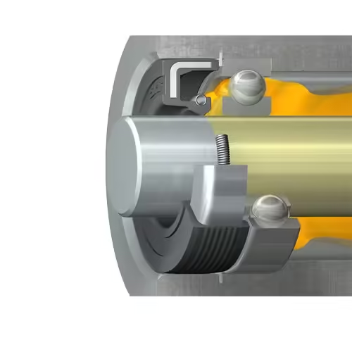
A conventional radial shaft seal uses an elastomer sealing lip that contacts the rotating shaft with controlled radial interference. Many designs also use a garter spring to maintain the required lip load.
At the contact zone, a very thin lubricating film helps control friction and temperature while the lip maintains the conditions needed to retain lubricant.
This is why a shaft that merely “looks smooth” is not necessarily a suitable oil seal counterface.
If the surface is too rough, surface peaks can accelerate lip wear. If the surface condition does not support appropriate lubrication, friction and temperature can increase. Directional machining marks can also influence fluid movement in rotary applications.
For conventional radial shaft seals, manufacturers publish counterface requirements covering surface roughness, machining method, lead, hardness, runout, and other parameters. These specifications should be checked against the actual seal design rather than replaced by one universal roughness value.
How a Small Surface Problem Can Develop into Leakage
A relatively small defect can start a much larger failure:
Surface defect → disturbed lip contact or lubricating film → increased lip wear or initial leakage → heat/contamination → accelerated shaft and seal damage
Consider an axial scratch crossing the sealing track.
Initially, it may create only a small leakage path underneath the lip. Once leakage or contamination begins, conditions at the contact interface deteriorate. Lip wear increases, the contact band changes, and additional shaft wear may follow.
By teardown, the original scratch may no longer look like the most serious damage.
That is why failure diagnosis should reconstruct the sequence rather than simply identify the worst-looking component.
When Shaft Surface Damage Comes First
Some shaft conditions can quickly damage an otherwise correctly selected oil seal.
Wear Grooves from Previous Service
Circumferential wear grooves are commonly found during oil seal replacement.
After long service, the previous seal may leave a distinct track at its contact position. If the replacement seal is installed at exactly the same depth, its lip may run directly in that existing groove.
The new lip then operates on a counterface that no longer has the intended geometry.
Depending on groove condition and seal design, the result can include:
- Uneven lip loading
- Poor circumferential contact
- Disturbed lubrication at the contact band
- Accelerated lip wear
- Early leakage
This is one reason a new oil seal may leak shortly after replacement even when its material and nominal dimensions are correct.
However, there is an important diagnostic warning:
Do not assume the deepest groove is the original cause.
The groove may itself be secondary evidence of an earlier sealing-system problem. Contamination, dry running, excessive temperature, inappropriate surface finish, runout, or excessive lip loading may have created the wear track during previous service.
The groove tells you that the counterface has been damaged. It does not automatically tell you why.
Scratches, Tool Marks, and Handling Damage
Scratches become particularly dangerous when they cross the sealing path.
An axial or diagonal scratch can pass underneath the sealing lip and create a direct leakage channel.
Common sources include:
- Shaft machining
- Improper polishing or refinishing
- Bearing or coupling removal
- Pry bars and removal tools
- Sharp assembly tools
- Transport damage
- Poor handling during maintenance
A quick visual inspection is not always sufficient. The actual sealing track should be checked carefully before installing the new seal.
Do not judge the replacement seal before checking whether a scratch crosses its contact band.
Corrosion and Pitting
Corrosion creates an irregular counterface that prevents consistent lip contact.
This is especially relevant in machinery exposed to:
- Water
- Condensation
- Washdown
- Outdoor environments
- Humidity
- Long storage periods
Pits underneath the lip interrupt the sealing surface and may also trap moisture or abrasive contamination.
Equipment that has been stored for months can therefore have a poor sealing surface even when it has accumulated very few operating hours.
Incorrect Shaft Surface Finish
Surface finish is a functional part of the sealing system.
An excessively rough surface can abrade the elastomer lip. An unsuitable polishing or machining pattern can influence lubricant behavior at the interface. A surface that is excessively smooth for the specific application may also affect lubrication and friction.
The correct shaft finish should follow the selected seal manufacturer’s requirements.
For many conventional radial shaft seals, published guidance commonly specifies tightly controlled roughness and recommends manufacturing methods such as plunge grinding to minimize directional lead. But one numerical roughness range should not be applied automatically to every rotary seal.
Seal material, shaft material, speed, lubrication, pressure, and lip design all affect the final requirement.
| Shaft Condition | Effect at Seal Lip | Typical Leakage Risk | Recommended Corrective Action |
|---|---|---|---|
| Existing wear groove | Changes lip contact geometry | Early or repeat leakage | Reposition, repair, sleeve or replace as appropriate |
| Axial/angled scratch | Creates path across sealing contact | Direct leakage | Repair or restore counterface |
| Corrosion/pitting | Interrupts continuous contact | Leakage and accelerated wear | Restore or replace damaged surface |
| Excessive roughness | Abrades sealing lip | Progressive leakage | Refinish to specified condition |
| Directional machining pattern | May influence fluid movement | Dynamic leakage | Correct machining method/surface |
| Excessive runout | Produces changing lip contact | Uneven wear and leakage | Check shaft geometry and alignment |
When Oil Seal Failure Damages the Shaft First
Finding a shaft groove does not prove that the shaft was defective before the seal failed.
The sealing system itself can initiate shaft deterioration.
Insufficient Lubrication and Dry Running
The sealing lip requires appropriate lubrication at the dynamic contact interface.
When lubrication is insufficient, friction increases.
Higher friction produces localized heat. Depending on the elastomer and operating conditions, the lip can harden, glaze, crack, or wear. At the same time, the deteriorating contact condition can accelerate shaft wear.
This can occur during startup when lubricant does not reach the lip quickly enough or in applications where the sealing arrangement does not maintain adequate lubrication during operation.
If a shaft groove is found together with a hardened or heavily worn lip, do not investigate shaft hardness alone.
Check how the lip was lubricated.
Excessive Lip Load or Incorrect Seal Selection
The sealing lip needs sufficient radial force to maintain its function, but excessive contact force is not an advantage.
Potential causes include:
- Incorrect seal dimensions
- Excessive interference
- Inappropriate lip geometry
- Incorrect spring condition
- Seal design unsuitable for shaft speed
- Operating pressure beyond the seal’s intended capability
Excessive lip load increases friction and can raise contact temperature.
This is why selecting an oil seal only by shaft diameter × housing bore × width can be inadequate for demanding applications.
The dimensions tell the supplier what fits.
They do not necessarily tell the supplier what will survive.
Excessive Temperature
Two temperatures matter during oil seal troubleshooting.
The first is the bulk operating temperature of the oil, gearbox, motor, pump, or surrounding equipment.
The second is the local contact temperature generated where the sealing lip runs on the shaft.
These are not necessarily the same.
A seal can experience damaging contact temperature even when the measured oil temperature appears acceptable.
Depending on the compound and exposure conditions, excessive heat can lead to:
- Hardening
- Loss of elasticity
- Cracking
- Accelerated wear
- Permanent lip deformation
Visible shaft deterioration may develop later.
Abrasive Contamination at the Seal-Shaft Interface
Dust, sand, mud, metal particles, and process debris can turn the sealing interface into an abrasive wear zone.
A typical sequence is:
Contamination reaches lip → particles become trapped → abrasive wear increases → shaft groove develops → sealing contact deteriorates → leakage accelerates
This is particularly important in agricultural machinery, construction equipment, mining equipment, outdoor machinery, and other dirty environments.
If contamination is the real problem, changing only the elastomer grade may have little effect.
The equipment may require better exclusion of external contaminants, an auxiliary dust lip, or a different sealing arrangement.
Installation Damage That Starts the Failure Cycle
Some oil seal failures begin before the shaft makes its first revolution.
The lip can be damaged by:
- Sharp shaft edges
- Keyways
- Splines
- Threads
- Incorrect installation tools
- Angled installation
- Lip rolling or folding
- Incorrect installation depth
If the lip is cut during assembly, leakage may later be blamed on the seal material or shaft surface.
Do not evaluate seal quality without checking how the seal passed over keyways, splines, threads, shoulders, and shaft edges during installation.
The Feedback Loop: Why the Original Cause Becomes Difficult to Identify
This is the central difficulty in shaft damage vs oil seal failure diagnosis.
The shaft and lip continuously influence each other.
One sequence may be:
Initial shaft scratch → lip damage → leakage → lubricant loss or contamination → additional lip and shaft wear
Another may be:
Initial lubrication or seal problem → excessive friction/abrasion → shaft groove → reduced sealing contact → increased leakage
After enough operating time, the final appearance of these two failures may be very similar.
A badly worn shaft can therefore be secondary damage rather than the initiating cause.
Likewise, a badly damaged oil seal does not prove that the seal itself was defective.
The most visible damage at teardown is evidence—but it is not automatically the root cause.
How to Determine Which Failure Came First
A good failure inspection preserves evidence first and repairs the machine second.
Step 1 — Inspect the Shaft Before Cleaning or Polishing It
After removing the seal, document the shaft before altering the surface.
Check:
- Exact location of the wear track
- Circumferential grooves
- Axial or diagonal scratches
- Corrosion and pitting
- Heat discoloration
- Deposits
- Abrasive contamination
- Multiple historical seal tracks
Take close-up photos.
If possible, mark the original seal position before further disassembly.
Do not polish away the evidence before taking photos and recording the wear position.
Multiple wear tracks can be particularly useful because they may reveal previous installation depths and repair attempts.
Step 2 — Inspect the Removed Seal Lip
Do not throw the failed seal away immediately.
Check the complete circumference for:
- Hardening
- Cracking
- Chipping
- Excessive polished wear
- Uneven wear
- Embedded particles
- Lip inversion
- Rolling or deformation
- Heat-related appearance changes
Uneven wear can be especially useful evidence.
If one section is heavily worn while another is relatively intact, investigate runout, eccentricity, misalignment, installation position, and local shaft defects.
Step 3 — Compare the Seal Contact Band with the Shaft Damage
Put the seal and shaft evidence together.
Does the damaged lip position correspond with a groove?
Does an axial scratch pass through the exact sealing track?
Does the wear band show that the seal was installed at a different depth from the intended position?
Does the shaft have multiple historical tracks?
Matching the physical positions can help reconstruct what happened before leakage became severe.
Step 4 — Review Operating Conditions
Now compare the physical evidence with actual machine conditions.
Check:
- Shaft speed
- Continuous operating temperature
- Peak temperature
- Pressure
- Lubricant
- Lubrication availability at the lip
- External contamination
- Shaft runout
- Misalignment
- Operating hours
- Duty cycle
- Previous seal life
A good diagnosis often comes from several clues pointing in the same direction rather than one obvious defect.
Step 5 — Review the Previous Repair
Repeated leakage deserves a review of the last repair.
Ask:
- Was only the oil seal replaced?
- Was the shaft sealing track inspected?
- Was the shaft measured?
- Did the new lip run in an existing groove?
- Was installation depth changed?
- Was the correct installation tool used?
- Was the lip protected while passing over shaft features?
- Was initial lubrication provided correctly?
- Did leakage return immediately?
- Or did it appear after a period of operation?
Failure timing provides useful clues.
Immediate leakage may point toward an existing shaft defect, incorrect dimensions, damaged lip, incorrect installation, or assembly error.
Progressive leakage may be more consistent with wear, contamination, lubrication problems, temperature, runout, or changing operating conditions.
| Inspection Evidence | Possible Initial Cause | Possible Secondary Damage | Recommended Checks |
|---|---|---|---|
| Axial scratch beneath lip | Shaft damage | Lip wear and leakage | Previous machining/repair history |
| Hardened lip with relatively new shaft | Heat or dry running | Shaft contact wear | Lubrication and temperature |
| Groove plus embedded particles | Contamination | Abrasive lip and shaft wear | External environment and exclusion system |
| Uneven circumferential wear | Runout/misalignment | Local lip wear | Shaft geometry and installation |
| Cut lip after short service | Installation damage | Leakage and contamination | Keyways, splines, tools and lead-in |
| Old groove with new seal leakage | Previous shaft wear | Rapid new-lip deterioration | Seal contact position and shaft repair |
Can You Install a New Oil Seal on a Worn Shaft?
Sometimes, but a new seal should not automatically be installed simply because it still fits the nominal shaft diameter.
The decision depends on:
- Groove severity
- Remaining surface condition
- Shaft dimensional condition
- Shaft material
- Equipment criticality
- Seal design
- Available axial installation position
- Repair economics
- Consequence of another leak
There is no universal groove-depth threshold that determines whether every shaft can be reused.
Option 1 — Reposition the Seal Lip
In some assemblies, changing the axial installation depth allows the new lip to run on an undamaged portion of the shaft.
This can be an economical repair when a suitable adjacent counterface is available.
But first check:
- Housing geometry
- Seal width
- Internal clearance
- Shoulder positions
- Lubrication access
- Manufacturer requirements
Moving the lip away from one problem should not create another.
Option 2 — Repair or Refinish the Shaft
A repairable shaft may be restored through a controlled machining or surface-repair process.
The important word is controlled.
The final surface must work as a dynamic seal counterface. Diameter, roundness, surface texture, machining direction, and hardness where relevant must remain suitable for the application.
Do not hand-polish a damaged shaft until it looks shiny and assume the sealing problem is solved.
Appearance is not the specification.
Option 3 — Use a Shaft Repair Sleeve
A shaft repair sleeve provides a new running surface over a localized worn area and can avoid replacing the complete shaft.
This is often attractive for maintenance work when:
- The wear is localized around the seal track
- The main shaft remains mechanically serviceable
- Removing or manufacturing a replacement shaft would create significant downtime
- A suitable sleeve size and sealing arrangement are available
Before using a sleeve, verify:
- Shaft dimensions
- Sleeve fit
- Final running diameter
- Surface condition
- Seal compatibility
- Installation method
- Operating speed and conditions
A repair sleeve restores the running surface.
It does not explain why the original surface failed.
If contamination, dry running, excessive temperature, or runout caused the original groove, those conditions still need attention.
Option 4 — Replace the Shaft
Shaft replacement becomes more appropriate when there is:
- Severe wear
- Extensive corrosion
- Major dimensional damage
- Multiple damaged sealing positions
- Structural damage
- Insufficient material for controlled repair
- High equipment criticality where repair uncertainty is unacceptable
Replacement normally involves higher cost and downtime, but it may be the safer decision when the original counterface cannot be restored reliably.
| Shaft Condition | Possible Solution | Main Advantage | Main Limitation |
|---|---|---|---|
| Minor issue with usable adjacent track | Reposition seal | Low repair cost | Requires suitable alternative contact area |
| Repairable surface damage | Refinish/repair | Restores counterface | Requires dimensional and surface control |
| Localized wear groove | Repair sleeve | May avoid shaft replacement | Fit and seal compatibility must be verified |
| Severe or extensive damage | Replace shaft | Restores shaft geometry | Higher cost and downtime |
Do not install another seal into the same damaged groove without a repair plan.
Why Replacing the Oil Seal Alone Often Does Not Stop Repeat Leakage
This is a common and expensive maintenance cycle:
- Oil leakage appears.
- The old seal is removed.
- A replacement seal of the same size is installed.
- The shaft sealing track is not properly inspected.
- The new lip runs on the existing groove or damaged surface.
- Leakage returns.
- The replacement seal is assumed to be defective.
A different seal batch may then be tried.
Next, a different seal brand may be tried.
But if the shaft counterface remains unsuitable, changing suppliers does not restore the sealing surface.
Do not judge seal quality before checking the shaft track.
For MRO buyers and repair companies, this is particularly important when handling supplier complaints. A seal that leaks after short service should be evaluated together with the shaft, installation condition, operating data, and failed component.
Repeated failure requires seal-system diagnosis, not repeated component replacement.
Preventing Shaft and Oil Seal Damage in New Designs
During design review, do not specify the shaft and oil seal separately. Treat them as one working interface.
The drawing and seal specification should account for:
- Shaft material and hardness where relevant
- Counterface surface finish
- Machining direction
- Shaft runout
- Shaft speed
- Lubrication
- Operating temperature
- Pressure
- External contamination
- Seal material
- Lip geometry
For conventional radial shaft seals, DIN 3760 / DIN 3761 or relevant seal-manufacturer specifications may provide useful dimensional and design guidance where applicable.
They should not be treated as universal specifications for every rotary sealing arrangement.
Match Seal Material to the Actual Operating Environment
Material selection should follow the application rather than a simple idea that a more expensive compound is automatically better.
NBR is widely used for oil seals because it offers a practical balance of oil resistance, mechanical performance, and cost under many moderate service conditions.
FKM is often considered when higher temperatures or more demanding chemical conditions require it.
Other compounds or sealing materials may be needed for specialized media or operating environments.
The decision should be based on the actual combination of:
medium + temperature + speed + pressure + lubrication + seal design + expected service conditions
Changing from NBR to FKM will not repair a shaft groove.
Likewise, repairing the shaft will not correct an elastomer that is incompatible with the lubricant or operating temperature.
What Buyers Should Provide When Repeated Oil Seal Failure Occurs
When requesting technical support, sending only an oil seal size such as 40 × 60 × 10 mm is usually not enough to diagnose repeated failure.
Provide:
- Oil seal dimensions or drawing
- Existing seal type and lip design
- Seal material
- Shaft diameter
- Shaft material
- Shaft condition
- Available shaft surface specification
- Shaft speed or RPM
- Continuous operating temperature
- Peak temperature
- Pressure
- Lubricating medium
- External contamination
- Equipment type
- Photos of the failed seal
- Close-up photos of the shaft wear track
- Failure interval or approximate service hours
- Installation method
- Whether the problem has happened repeatedly
These details allow a seal manufacturer to determine whether the next step should involve a material change, different lip design, shaft correction, better contamination protection, installation change, or a customized sealing solution.
For repeat failures, send photos of both the failed seal and the shaft track whenever possible.
A picture of the oil leak alone rarely provides enough evidence.
Typical Failure Scenario: Repeated Leakage After Oil Seal Replacement
Consider a common maintenance situation.
A gearbox develops leakage around the shaft. The maintenance team removes the old radial oil seal and installs another seal with the same nominal dimensions.
The gearbox returns to service.
Shortly afterward, oil appears around the shaft again.
The replacement seal may be suspected immediately, but several other mechanisms need to be ruled out.
Likely Risk Factors to Investigate
Check whether:
- The new lip is running directly in an existing shaft groove.
- A scratch crosses the sealing track.
- Corrosion or pitting exists beneath the lip.
- Abrasive contamination is trapped at the interface.
- The seal was installed at an incorrect depth.
- The lip experienced dry startup.
- Shaft runout is excessive.
- The lip was damaged while passing over a keyway or spline.
- The elastomer is unsuitable for the actual temperature or lubricant.
- Operating pressure or speed exceeds the seal design.
More than one factor may be involved.
Recommended Checks Before Installing Another Seal
Before opening another replacement seal package, stop and inspect the system.
Document the shaft track.
Inspect the removed lip.
Match the lip position to the shaft wear.
Check installation depth.
Look for contamination.
Confirm lubrication.
Review speed, temperature, pressure, and runout.
If the shaft has an established groove, determine whether the lip can safely be repositioned or whether the shaft needs repair, a sleeve, or replacement.
If the shaft appears acceptable but the lip is hardened or heavily worn, investigate temperature and lubrication before installing the same solution again.
The objective is not to decide whether the seal or shaft looks worse.
The objective is to identify the first credible failure mechanism.
Buyer Decision Guide: Replace the Seal, Repair the Shaft, or Change the Sealing Solution?
Replace the oil seal only when the shaft sealing surface remains acceptable and the evidence points to normal seal wear or an isolated seal problem.
Repair, reposition, sleeve, or replace the shaft when the counterface can no longer provide a reliable dynamic sealing surface.
Review the complete sealing system when failures continue despite correct shaft condition and proper installation. At this point, check speed, pressure, temperature, runout, lubrication, contamination, and seal design together.
Consider a custom oil seal solution when a standard seal cannot adequately handle the combination of media, speed, temperature, pressure, contamination, shaft geometry, or installation constraints.
For OEM projects, solving these conditions during design review is usually more economical than troubleshooting repeated leakage after the machine enters service.
Frequently Asked Questions About Shaft Damage and Oil Seal Failure
1. Can an oil seal wear a groove into a shaft?
Yes.
A radial oil seal operates in continuous contact with the rotating shaft, so wear can develop at the contact band over time. The risk increases when lubrication is insufficient, abrasive particles become trapped under the lip, contact temperature is excessive, lip loading is inappropriate, or the shaft surface is not suitable for the application.
However, finding a groove does not automatically prove that the oil seal itself was defective.
The groove may be the result of contamination, dry running, excessive friction, shaft material or surface issues, or a combination of several conditions.
When a groove is found, inspect both the groove and the removed lip before deciding what caused it.
2. Can a worn shaft cause a new oil seal to leak?
Yes. This is a common cause of repeat leakage after seal replacement.
If the new sealing lip runs directly in an existing wear groove, scratch, corroded area, or damaged counterface, it may not establish consistent contact with the shaft.
Leakage can then appear shortly after installation even though the new seal has the correct nominal dimensions.
Before replacing an oil seal, inspect the exact shaft contact track.
A new seal cannot compensate for every damaged shaft surface.
3. How can you tell whether the shaft or oil seal failed first?
There is rarely one visual clue that proves the sequence.
Compare several types of evidence:
- Shaft groove location and shape
- Axial or diagonal scratches
- Corrosion and pitting
- Seal lip hardening or cracking
- Uneven lip wear
- Embedded abrasive particles
- Contact-band position
- Lubrication condition
- Temperature exposure
- Installation history
- Previous seal life
- Shaft runout and operating conditions
For example, a clear shaft scratch underneath the sealing track may indicate that shaft damage initiated the failure. A relatively new shaft combined with a hardened, heat-damaged lip may instead point toward lubrication or temperature problems.
Do not use the severity of the final damage as proof of the failure sequence.
4. Why does a new oil seal still leak after replacement?
A new oil seal can leak when the original root cause was never corrected.
Common reasons include:
- Existing shaft groove
- Shaft scratch or corrosion
- Incorrect installation
- Lip damage during assembly
- Dry startup
- Excessive runout
- Contamination
- Incorrect seal material
- Excessive temperature
- Excessive pressure or shaft speed
- Wrong seal design for the application
If several replacement seals fail in the same position, stop treating the problem as routine seal replacement.
The shaft and operating system should be investigated together.
5. Can a new oil seal run on an existing shaft groove?
It may physically run in the groove, but that does not mean it will provide reliable sealing.
An existing groove changes the geometry of the contact surface and may prevent the new lip from maintaining the intended contact condition.
Depending on the application, possible solutions include repositioning the seal so the lip runs on an undamaged track, refinishing the shaft, installing a suitable repair sleeve, or replacing the shaft.
Do not install another seal into the same groove simply because the previous seal was installed there.
The shaft condition should first be evaluated against the requirements of the selected seal.
6. When should a shaft repair sleeve be used?
A repair sleeve is worth considering when wear is concentrated around the oil seal contact track but the rest of the shaft remains mechanically serviceable.
It can be particularly useful when replacing or machining the complete shaft would create significant cost or downtime.
Before selecting a sleeve, verify:
- Actual shaft diameter
- Location and extent of wear
- Sleeve dimensions and fit
- Final sealing diameter
- Seal compatibility
- Sleeve surface quality
- Installation method
- Operating speed and temperature
A sleeve can restore the sealing surface, but it should not be treated as the complete root-cause solution.
If abrasive contamination, dry running, runout, or excessive temperature created the original groove, correct that condition as well.
Final Takeaway: Diagnose the Failure Sequence Before Replacing Parts
Shaft damage vs oil seal failure is not a simple question of which component looks worse.
A scratched, worn, corroded, grooved, or incorrectly finished shaft can damage an oil seal. At the same time, dry running, contamination, excessive heat, inappropriate seal selection, or installation problems can damage the lip first and subsequently wear the shaft.
The key is to separate initial failure from secondary damage.
Before replacing parts:
Do not assume the deepest groove is the original cause.
Do not judge seal quality before checking the shaft track.
Do not polish away evidence before taking photos.
Do not install another seal into the same damaged groove without a repair plan.
For repeated oil seal leakage, inspect the shaft surface, removed lip, contact position, lubrication, contamination, installation condition, and operating history as one system.
If you are experiencing repeated oil seal leakage or shaft wear, DRO Rubber Seals can review the application based on your seal dimensions, shaft information, operating conditions, and failure photos. These details help determine whether the next step should be a different seal material, lip design, shaft repair, installation change, or customized sealing solution.
Website: drorubber.com
WhatsApp: +0086 15815831911
WeChat: +0086 13784044874